


Variant Details


64 Variants
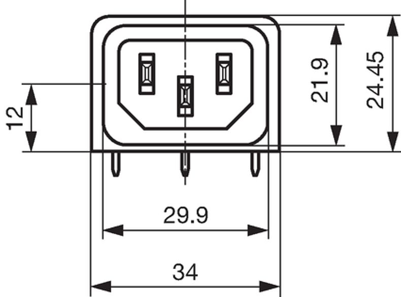
C14
70° C |
Newly available variants corresponding to V-Lock mating cordset. The connector is equipped with a notch intended for use with the latching cordset. The cord latching system prevents against accidental removal of the cordset.
Ratings IEC
10 A / 250 VAC; 50 Hz
Ratings UL/CSA
10 A / 250 VAC; 60 Hz
without fuseholder 16A (UL)
Dielectric Strength
> 3 kVAC between L-N
> 4 kVAC between L/N-PE
(1 min/50 Hz)
Allowable Operation Temperature
-25 °C to 70 °C
IP-Protection
front side IP40 acc. to IEC 60529
Protection against electric shock
Suitable for appliances with protection class I acc. to IEC 61140
Terminal
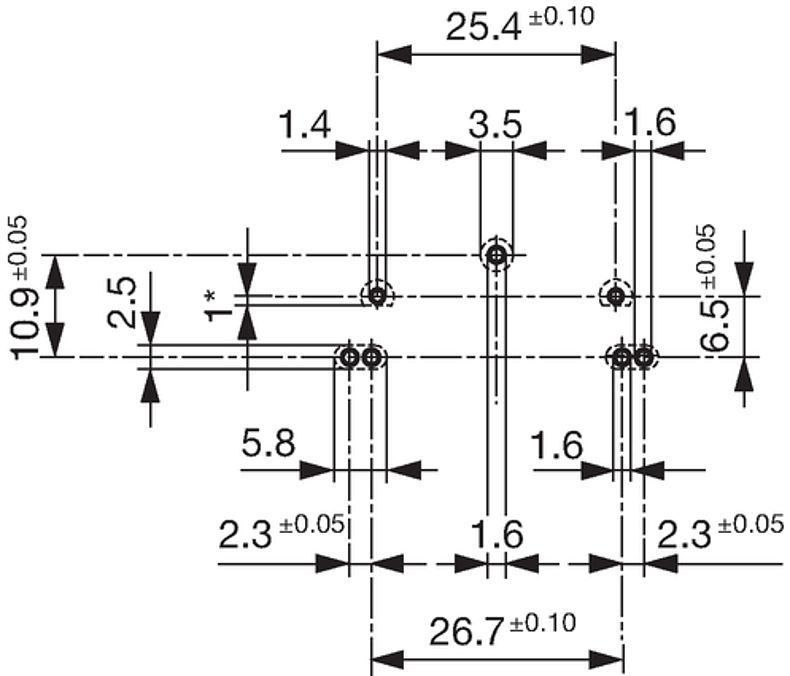
For PCB mounting
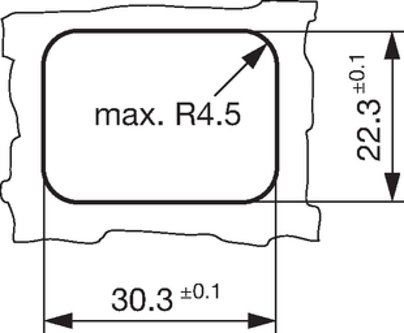
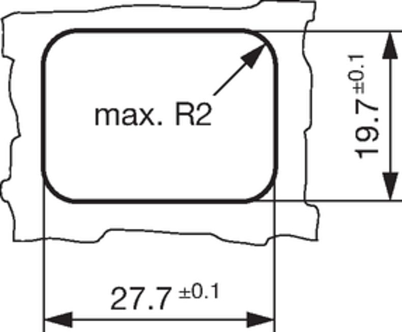
Panel Thickness S
Screw: max 6 mm
Mounting screw torque max 0.3 Nm
Snap-in: 1.5/2/2.5/3 mm
Material: Housing
Thermoplastic, black, UL 94V-0
Appliance inlet/-outlet
C14 acc. to IEC 60320-1,
UL 498, CSA C22.2 no. 42 (for cold conditions) pin-temperature 70 °C, 10 A, Protection Class I
Fuseholder
1-/2-pole, Shocksafe category PC2 acc. to IEC 60127-6,
for fuse-links 5 x 20 mm
Rated Power Acceptance @ Ta 23 °C
5 x 20: 3.15 W (1 pole)/ 2.5 W (2-pole) per pole
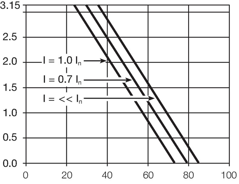
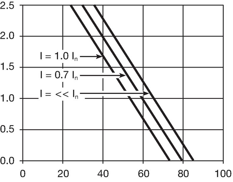
Power Acceptance @ Ta > 23°C
Admissible power acceptance at higher ambient temperature see derating curves
Detailed information on product approvals, code requirements, usage instructions and detailed test conditions can be looked up in
Details about Approvals
SCHURTER products are designed for use in industrial environments. They have approvals from independent testing bodies according to national and international standards. Products with specific characteristics and requirements such as required in the automotive sector according to IATF 16949, medical technology according to ISO 13485 or in the aerospace industry can be offered exclusively with customer-specific, individual agreements by SCHURTER.
The approval mark is used by the testing authorities to certify compliance with the safety requirements placed on electronic products.
Approval Reference Type: GSF1
| Approval Logo | Certificates | Certification Body | Description |
|---|---|---|---|

|
VDE | Certificate Number: 40024857 | |

|
UL | UR File Number: E93617, E96454 | |

|
CCC | CCC Certificate Number: 2020180204013041 |
Product standards that are referenced
| Organization | Design | Standard | Description |
|---|---|---|---|
| Designed according to | IEC 60320-1 | Appliance couplers for household and similar general purposes | |
| Designed according to | IEC 60127-6 | Miniature fuses. Part 6. Fuse-holders for miniature fuse-links | |
| Designed according to | IEC 61058-1 | Switches for appliances. Part 1. General requirements | |
| Designed according to | UL 498 | Standard for Attachment Plugs and Receptacles | |
| Designed according to | CSA C22.2 no. 42 | General Use Receptacles, Attachment Plugs, and Similar Wiring Devices |
Application standards where the product can be used
| Organization | Design | Standard | Description |
|---|---|---|---|
| Suitable for applications acc. | IEC/UL 62368-1 | Audio/video, information and communication technology equipment - Part 1: Safety requirements | |
| Suitable for applications acc. | IEC 60335-1 | Safety of electrical appliances for household and similar purposes. Meets the requirements for appliances in unattended use. This includes the enhanced requirements of glow wire tests acc. to IEC 60695-2-11 or -12 & -13. |
The product complies with following Guide Lines
| Identification | Details | Initiator | Description |
|---|---|---|---|

|
SCHURTER AG | The CE marking declares that the product complies with the applicable requirements laid down in the harmonisation of Community legislation on its affixing in accordance with EU Regulation 765/2008. | |

|
SCHURTER AG | The UKCA marking declares that the product complies with the applicable requirements laid down in the British Amendment of Regulation (EC) 765/2008. | |

|
SCHURTER AG | Directive RoHS 2011/65/EU, Amendment (EU) 2015/863 | |

|
SCHURTER AG | The law SJ / T 11363-2006 (China RoHS) has been in force since 1 March 2007. It is similar to the EU directive RoHS. | |

|
SCHURTER AG | ||

|
SCHURTER AG | Meets the requirements of IEC 60335-1 for appliances in unattended use. This includes the enhanced requirements of glow wire tests acc. to IEC 60695-2-11 or -12 &-13. |
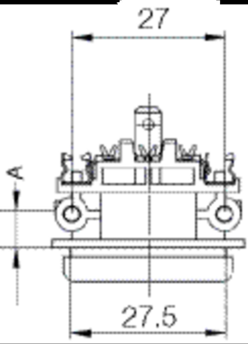
| A = 6 mm for standard versions A = 5 mm for pick and place versions S = 0 mm for mounting from rear-side |
| Mounting side | Panel mounting | Panel Thickness s [mm] |
Order Number
Variant Details
|
A=Most Popular | Free Sample | Distributor Stock Check | ... | |||||||||||||||||||||||||||||||||||||||||||||||||||||||||||||||||||||||||||||||||||||||||||
|---|---|---|---|---|---|---|---|---|---|---|---|---|---|---|---|---|---|---|---|---|---|---|---|---|---|---|---|---|---|---|---|---|---|---|---|---|---|---|---|---|---|---|---|---|---|---|---|---|---|---|---|---|---|---|---|---|---|---|---|---|---|---|---|---|---|---|---|---|---|---|---|---|---|---|---|---|---|---|---|---|---|---|---|---|---|---|---|---|---|---|---|---|---|---|---|---|---|---|
| Sandwich | Snap-in | 1.5 | GSF1.0201.31 | ... | ||||||||||||||||||||||||||||||||||||||||||||||||||||||||||||||||||||||||||||||||||||||||||||||
| Sandwich | Snap-in | 2 | GSF1.0201.41 | ... | ||||||||||||||||||||||||||||||||||||||||||||||||||||||||||||||||||||||||||||||||||||||||||||||
| Sandwich | Snap-in | 2.5 | GSF1.0201.51 | ... | ||||||||||||||||||||||||||||||||||||||||||||||||||||||||||||||||||||||||||||||||||||||||||||||
| Sandwich | Snap-in | 3 | GSF1.0201.61 | ... | ||||||||||||||||||||||||||||||||||||||||||||||||||||||||||||||||||||||||||||||||||||||||||||||
| Sandwich | Snap-in | 1.5 | GSF1.0202.31 | ... | ||||||||||||||||||||||||||||||||||||||||||||||||||||||||||||||||||||||||||||||||||||||||||||||
| Sandwich | Snap-in | 2 | GSF1.0202.41 | ... | ||||||||||||||||||||||||||||||||||||||||||||||||||||||||||||||||||||||||||||||||||||||||||||||
| Sandwich | Snap-in | 2.5 | GSF1.0202.51 | ... | ||||||||||||||||||||||||||||||||||||||||||||||||||||||||||||||||||||||||||||||||||||||||||||||
| Sandwich | Snap-in | 3 | GSF1.0202.61 | ... | ||||||||||||||||||||||||||||||||||||||||||||||||||||||||||||||||||||||||||||||||||||||||||||||
| Sandwich | Snap-in | 1.5 | GSF1.1201.31 | ... | ||||||||||||||||||||||||||||||||||||||||||||||||||||||||||||||||||||||||||||||||||||||||||||||
| Sandwich | Snap-in | 2 | GSF1.1201.41 | ... | ||||||||||||||||||||||||||||||||||||||||||||||||||||||||||||||||||||||||||||||||||||||||||||||
| Sandwich | Snap-in | 2.5 | GSF1.1201.51 | ... | ||||||||||||||||||||||||||||||||||||||||||||||||||||||||||||||||||||||||||||||||||||||||||||||
| Sandwich | Snap-in | 3 | GSF1.1201.61 | ... | ||||||||||||||||||||||||||||||||||||||||||||||||||||||||||||||||||||||||||||||||||||||||||||||
| Sandwich | Snap-in | 1.5 | GSF1.1202.31 | ... | ||||||||||||||||||||||||||||||||||||||||||||||||||||||||||||||||||||||||||||||||||||||||||||||
| Sandwich | Snap-in | 2 | GSF1.1202.41 | ... | ||||||||||||||||||||||||||||||||||||||||||||||||||||||||||||||||||||||||||||||||||||||||||||||
| Sandwich | Snap-in | 2.5 | GSF1.1202.51 | ... | ||||||||||||||||||||||||||||||||||||||||||||||||||||||||||||||||||||||||||||||||||||||||||||||
| Sandwich | Snap-in | 3 | GSF1.1202.61 | ... | ||||||||||||||||||||||||||||||||||||||||||||||||||||||||||||||||||||||||||||||||||||||||||||||
| Sandwich | Snap-in | 1.5 | GSF1.2201.31 | ... | ||||||||||||||||||||||||||||||||||||||||||||||||||||||||||||||||||||||||||||||||||||||||||||||
| Sandwich | Snap-in | 2 | GSF1.2201.41 | ... | ||||||||||||||||||||||||||||||||||||||||||||||||||||||||||||||||||||||||||||||||||||||||||||||
| Sandwich | Snap-in | 2.5 | GSF1.2201.51 | ... | ||||||||||||||||||||||||||||||||||||||||||||||||||||||||||||||||||||||||||||||||||||||||||||||
| Sandwich | Snap-in | 3 | GSF1.2201.61 | ... | ||||||||||||||||||||||||||||||||||||||||||||||||||||||||||||||||||||||||||||||||||||||||||||||
| Sandwich | Snap-in | 1.5 | GSF1.2202.31 | A | ... | |||||||||||||||||||||||||||||||||||||||||||||||||||||||||||||||||||||||||||||||||||||||||||||
| Sandwich | Snap-in | 2 | GSF1.2202.41 | ... | ||||||||||||||||||||||||||||||||||||||||||||||||||||||||||||||||||||||||||||||||||||||||||||||
| Sandwich | Snap-in | 2.5 | GSF1.2202.51 | ... | ||||||||||||||||||||||||||||||||||||||||||||||||||||||||||||||||||||||||||||||||||||||||||||||
| Sandwich | Screw | 1.5 | GSF1.0001.31 | ... | ||||||||||||||||||||||||||||||||||||||||||||||||||||||||||||||||||||||||||||||||||||||||||||||
| Sandwich | Screw | 2 | GSF1.0001.41 | ... | ||||||||||||||||||||||||||||||||||||||||||||||||||||||||||||||||||||||||||||||||||||||||||||||
| Sandwich | Screw | 2.5 | GSF1.0001.51 | ... | ||||||||||||||||||||||||||||||||||||||||||||||||||||||||||||||||||||||||||||||||||||||||||||||
| Sandwich | Screw | 3 | GSF1.0001.61 | ... | ||||||||||||||||||||||||||||||||||||||||||||||||||||||||||||||||||||||||||||||||||||||||||||||
| Sandwich | Screw | 1.5 | GSF1.0002.31 | ... | ||||||||||||||||||||||||||||||||||||||||||||||||||||||||||||||||||||||||||||||||||||||||||||||
| Sandwich | Screw | 2 | GSF1.0002.41 | ... | ||||||||||||||||||||||||||||||||||||||||||||||||||||||||||||||||||||||||||||||||||||||||||||||
| Sandwich | Screw | 2.5 | GSF1.0002.51 | ... | ||||||||||||||||||||||||||||||||||||||||||||||||||||||||||||||||||||||||||||||||||||||||||||||
| Sandwich | Screw | 3 | GSF1.0002.61 | ... | ||||||||||||||||||||||||||||||||||||||||||||||||||||||||||||||||||||||||||||||||||||||||||||||
| Sandwich | Screw | 2.5 | 3-104-974 | ... | ||||||||||||||||||||||||||||||||||||||||||||||||||||||||||||||||||||||||||||||||||||||||||||||
| Sandwich | Screw | 1.5 | GSF1.1001.31 | ... | ||||||||||||||||||||||||||||||||||||||||||||||||||||||||||||||||||||||||||||||||||||||||||||||
| Sandwich | Screw | 2 | GSF1.1001.41 | ... | ||||||||||||||||||||||||||||||||||||||||||||||||||||||||||||||||||||||||||||||||||||||||||||||
| Sandwich | Screw | 2.5 | GSF1.1001.51 | ... | ||||||||||||||||||||||||||||||||||||||||||||||||||||||||||||||||||||||||||||||||||||||||||||||
| Sandwich | Screw | 3 | GSF1.1001.61 | ... | ||||||||||||||||||||||||||||||||||||||||||||||||||||||||||||||||||||||||||||||||||||||||||||||
| Sandwich | Screw | 1.5 | GSF1.1002.31 | A | ... | |||||||||||||||||||||||||||||||||||||||||||||||||||||||||||||||||||||||||||||||||||||||||||||
| Sandwich | Screw | 2 | GSF1.1002.41 | ... | ||||||||||||||||||||||||||||||||||||||||||||||||||||||||||||||||||||||||||||||||||||||||||||||
| Sandwich | Screw | 2.5 | GSF1.1002.51 | ... | ||||||||||||||||||||||||||||||||||||||||||||||||||||||||||||||||||||||||||||||||||||||||||||||
| Sandwich | Screw | 3 | GSF1.1002.61 | ... | ||||||||||||||||||||||||||||||||||||||||||||||||||||||||||||||||||||||||||||||||||||||||||||||
| Sandwich | Screw | 2.5 | GSF1.1006.51 | ... | ||||||||||||||||||||||||||||||||||||||||||||||||||||||||||||||||||||||||||||||||||||||||||||||
| Sandwich | Screw | 1.5 | GSF1.2001.31 | ... | ||||||||||||||||||||||||||||||||||||||||||||||||||||||||||||||||||||||||||||||||||||||||||||||
| Sandwich | Screw | 2 | GSF1.2001.41 | ... | ||||||||||||||||||||||||||||||||||||||||||||||||||||||||||||||||||||||||||||||||||||||||||||||
| Sandwich | Screw | 2.5 | GSF1.2001.51 | ... | ||||||||||||||||||||||||||||||||||||||||||||||||||||||||||||||||||||||||||||||||||||||||||||||
| Sandwich | Screw | 3 | GSF1.2001.61 | ... | ||||||||||||||||||||||||||||||||||||||||||||||||||||||||||||||||||||||||||||||||||||||||||||||
| Sandwich | Screw | 1.5 | GSF1.2002.31 | ... | ||||||||||||||||||||||||||||||||||||||||||||||||||||||||||||||||||||||||||||||||||||||||||||||
| Sandwich | Screw | 2 | GSF1.2002.41 | ... | ||||||||||||||||||||||||||||||||||||||||||||||||||||||||||||||||||||||||||||||||||||||||||||||
| Sandwich | Screw | 2.5 | GSF1.2002.51 | ... | ||||||||||||||||||||||||||||||||||||||||||||||||||||||||||||||||||||||||||||||||||||||||||||||
| Sandwich | Screw | 3 | GSF1.2002.61 | ... | ||||||||||||||||||||||||||||||||||||||||||||||||||||||||||||||||||||||||||||||||||||||||||||||
| Rear Side | Snap-in | 6 | GSF1.0201.01 | ... | ||||||||||||||||||||||||||||||||||||||||||||||||||||||||||||||||||||||||||||||||||||||||||||||
| Rear Side | Snap-in | 6 | GSF1.0202.01 | ... | ||||||||||||||||||||||||||||||||||||||||||||||||||||||||||||||||||||||||||||||||||||||||||||||
| Rear Side | Snap-in | 6 | GSF1.1201.01 | ... | ||||||||||||||||||||||||||||||||||||||||||||||||||||||||||||||||||||||||||||||||||||||||||||||
| Rear Side | Snap-in | 6 | GSF1.1202.01 | ... | ||||||||||||||||||||||||||||||||||||||||||||||||||||||||||||||||||||||||||||||||||||||||||||||
| Rear Side | Snap-in | 6 | GSF1.2201.01 | A | ... | |||||||||||||||||||||||||||||||||||||||||||||||||||||||||||||||||||||||||||||||||||||||||||||
| Rear Side | Snap-in | 6 | GSF1.2202.01 | ... | ||||||||||||||||||||||||||||||||||||||||||||||||||||||||||||||||||||||||||||||||||||||||||||||
| Rear Side | Screw | 6 | GSF1.0001.01 | ... | ||||||||||||||||||||||||||||||||||||||||||||||||||||||||||||||||||||||||||||||||||||||||||||||
| Rear Side | Screw | 6 | GSF1.0002.01 | A | ... | |||||||||||||||||||||||||||||||||||||||||||||||||||||||||||||||||||||||||||||||||||||||||||||
| Rear Side | Screw | 6 | GSF1.1001.01 | ... | ||||||||||||||||||||||||||||||||||||||||||||||||||||||||||||||||||||||||||||||||||||||||||||||
| Rear Side | Screw | 6 | GSF1.1002.01 | ... | ||||||||||||||||||||||||||||||||||||||||||||||||||||||||||||||||||||||||||||||||||||||||||||||
| Rear Side | Screw | 6 | GSF1.2001.01 | ... | ||||||||||||||||||||||||||||||||||||||||||||||||||||||||||||||||||||||||||||||||||||||||||||||
| Rear Side | Screw | 6 | GSF1.2002.01 | ... | ||||||||||||||||||||||||||||||||||||||||||||||||||||||||||||||||||||||||||||||||||||||||||||||
| Rear Side | Metal snaps | 6 | GSF1.3402.01 | ... | ||||||||||||||||||||||||||||||||||||||||||||||||||||||||||||||||||||||||||||||||||||||||||||||
| Rear Side | Metal snaps | 6 | GSF1.4402.01 | ... | ||||||||||||||||||||||||||||||||||||||||||||||||||||||||||||||||||||||||||||||||||||||||||||||
| Rear Side | Metal snaps | 6 | GSF1.5402.01 | A | ... | |||||||||||||||||||||||||||||||||||||||||||||||||||||||||||||||||||||||||||||||||||||||||||||
|
█ Most Popular. Optional blister tray packaging 250 Pcs |
||||||||||||||||||||||||||||||||||||||||||||||||||||||||||||||||||||||||||||||||||||||||||||||||||
| Packaging unit | 50 Pcs |

4787, Mounting: Screw-on mounting, Appliance Outlet: IEC Solder terminals, 10 A, Suitable for appliances with protection class I

4788, Mounting: Snap-in version, Appliance Outlet: IEC Solder / Quick Connect, 10 A, Suitable for appliances with protection class I

IEC Appliance Outlet F or H, Screw-on Mounting, Front Side, Solder, PCB or Quick-connect Terminal


